
Glow Discharge
REGULATED HIGH VOLTAGE POWER SUPPLY
-6kV, 1A
This series of power supplies can generate output that ranges from 3kV to 6kV, 3kW to 6kWand are housed in compact 19” racks to give a highly regulated output. These unit are typically used for glow discharge application.
 Download Datasheet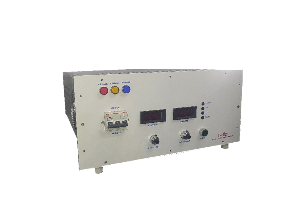
TECHNICAL SPECIFICATIONS
| PARAMETER | SPECIFICATION |
|---|---|
| Input Voltage | 415V±10% AC, 50Hz, three phase |
| Output Voltage | 0 to 6kV DC |
| Output Current | 0 to 1A |
| Polarity* | Negative |
| Voltage Regulation | Line regulation: ≤0.05% of full voltage and +500mv over the specified input range. Load regulation: ≤0.1% of full voltage and +500mv for no load to full load change. |
| Current Regulation | Line regulation: ≤ 0.1% of full current over the specified input range. Load regulation: ≤0.2% of full current and +/- 100uA for any voltage change. |
| Stability | ≤ 0.05%/hour after 1 hour warm up |
| Temperature Coefficient | < 0.05%/ºC |
| Regulating Mode | Constant voltage – constant current |
| Voltage & Current Control | Local: By 10-turn potentiometers with lockable counting dials on the front panel over entire range from zero to maximum rating Remote: Control through computer interface* |
| Protections* | Against over current, over voltage, over temperature, short-circuit and arc |
| Remote Controls & Signals through D-Connector (External RS232 Microcontroller Module) * | 10V DC reference 10V DC HV enable signal 0 to 10V DC signal for voltage & current control 0 to 10V DC signal for voltage & current monitoring |
| Cooling | Forced air |
| Front Panel | MCB for mains power ON/OFF with indication 3½ digit voltage and current meters 10-turn potentiometers for voltage and current control LED indication for faulty trip Push button to reset trip condition Constant voltage – constant current mode indication |
| Back Panel | Terminal block for mains input Fuse holders with fuse Terminals for output Stud for grounding the unit |
| Topology | High frequency resonant / PWM-controlled switch mode |
| Switching Device | IGBT |
| Cabinet | 19” rack, powder coated |
*Optional. To be specified by the user.
*Optional. RS232 interface available at an extra cost.
| Pins | 14 Pin Pluggable Connector (Analog Interface) | 25 Pin D Connector (PC Interface) |
|---|---|---|
| 1 | Earth | Earth |
| 2 | Common | Common |
| 3 | Interlock | HV Enable |
| 4 | HV Enable | Voltage Control Remote |
| 5 | Reference | Current Control Remote |
| 6 | Common | Over Voltage Control Remote* |
| 7 | Voltage Control Remote | Over Current Control Remote* |
| 8 | Voltage Control Local | Common |
| 9 | Common | Voltage Monitor |
| 10 | Current Control Remote | Current Monitor |
| 11 | Current Control Local | Reserved Monitor* |
| 12 | Common | Reserved Monitor* |
| 13 | Voltage Monitor | Common |
| 14 | Current Monitor | Mode Status |
| 15 | Interlock Status | |
| 16 | HV ON Status | |
| 17 | Common | |
| 18 | PS Fault Status* | |
| 19 | Over Voltage Status* | |
| 20 | Over Current Status* | |
| 21 | Over Temperature Status* | |
| 22 | Open Circuit Status* | |
| 23 | Phase Failure Status* | |
| 24 | Reserved Status* | |
| 25 | Common |